Laser and Topographical Surveys to measure motorway bridges on the A27 and M2
Home > Case Studies > Headroom Clearance Project for National Highways
01
Client requirements
National Highways asked us to carry out a series of specialised Laser and Topographical Surveys, in September 2022, as part of our ongoing contract with the client.
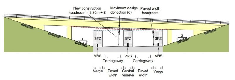
The task was to measure headroom clearances of four motorway bridges, and crosscheck them against the design and guidance manual for roads and bridges (CD127 cross-sections and headrooms).
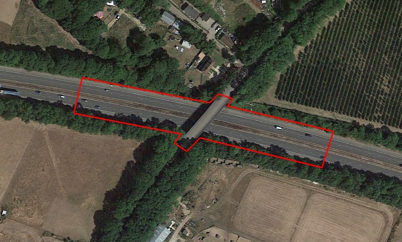
Three of the sites were located along the M2 between Rainham and Faversham in Kent, with the final site located on the A27 near Brighton.
02
40Seven Solution
We employed several different surveying methods to deliver the data.
We first used a mobile mapping approach to capture levels of all highway features, including drainage, carriageway levels, road markings, VRS, and kerb lines. We surveyed the approaching 100m area to each structure, as well as 100m past the structure, in both carriageway directions, to assist with future carriageway design.
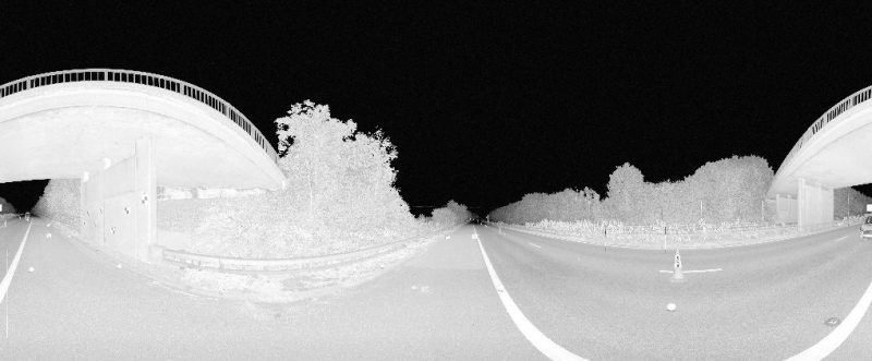
The structures and highways were surveyed using a vehicle-mounted laser scanner, eliminating the need for Traffic Management.
Then, a static Laser Scan Survey was then carried out under Traffic Management using an IPV and Lane 1 / Hardshoulder lane closures.
The Laser Scan Survey consisted of headroom measurements being captured at each lane demarcation; rib lines, lane dividers and more, as well as the boundary between the hard shoulder and any kerb lines, VRS or soft verge.
Two control stations were installed at each bridge, with various scans taken approximately 25m distance from the structure on either side to create a Point Cloud of the whole structure.
Road markings were also surveyed from each set up using a total station to provide ground control for the Mobile Mapping element.
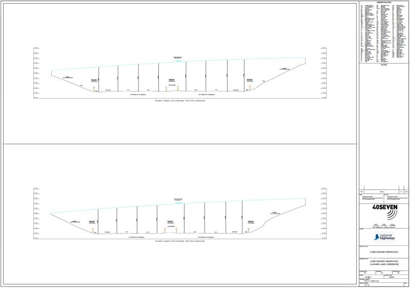
Using the Point Cloud generated from the Laser Scan data, measurements were taken under both the approach and departure edges of the bridges at the lowest edge of the bridge structure. The Structure Free Zone (SFZ) as defined in CD127 was also included, which consisted of the hard strips and verges between the carriageway, and bridge pier or wall. Measurements were taken in both carriageway directions, perpendicular to the carriageway.
The outputs for our client consisted of:
Cross-sections of each structure annotated with headroom measurements between approach and departure edges of the structure and carriageway level for all running lanes, including the boundary of hard shoulder, in both carriageway directions
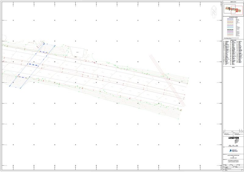
2D and 3D CAD drawing of all highway features, including levels
Longitudinal section drawings along each white line, 100m on approach and 100m on departure of the structure, in both carriageway directions
Sag curve radius calculations as outlined in CD127, determined from a 25 meter chord applied to the longitudinal sections. A moving 25 meter chord was used and the extents of the chord started 25 meters prior to the structure and ended 25 meters beyond the end of the structure. The minimum sag radius determined was also reported.
Industry-leading surveying services, delivering the right data at the right time.
We use cookies to ensure that we give you the best experience on our website. If you continue to use this site we will assume that you are happy with it.Ok